


The all-digital movement is winning over manufacturers seeking more automation, connectivity and reliability from their models and machines. Surveys from the Manufacturing Leadership Council and others show strong investments and results from Manufacturing 4.0 and related digital design and manufacturing initiatives. With a robust digital framework in place comes greater speed, depth, and agility in how product data is created and managed.
As impressive as interconnected digital-platform benefits are for traditional CAD/CAE/CAM disciplines, Computed Tomography (CT)-data analysis for quality inspection has greatly expanded its reach and purpose within today’s growing digital landscape. Its new influence on the central tools of design, simulation and manufacturing are significant; CT data analysis software is making these tools, normally used well upstream of it, even better in their roles.
Feedback from CT analysis to design and production
The establishment of Model-Based Definition (MBD) is increasingly guiding engineering beyond drawings and hybrid approaches. The move away from manual readings of data to MBD creates deeper and wider information threads throughout product development, from Product Manufacturing Information (PMI) files to machines and other programs.
It’s not just geometric annotations and manufacturing instructions that travel on digital threads. Companies are creating information loops to design, simulation and virtual testing that improve accuracy, conformance to specifications and shorten time-to-production.
These new development cycles are reinforcing a forty-year trend toward earlier and earlier decision making and less late-stage, at-production validation of products and methods of manufacture.
Setting the benchmark for quality inspection
It makes sense that a company engaged in connectivity and sensing solutions for electric vehicles, aircraft, digital-intelligent factories, wind and solar energy, cobots, IoT, high-speed connectivity and more, would invest in MBD and advanced inspection methods. With a stated goal of helping create transformational technology change grounded in reliable and durable electronics products, TE Connectivity is serious about engineered quality.
That “engineered” path brings to bear the advantages of ISO Geometric Product Specification (GPS) standards and virtual metrology against the limits of using classic design workflows. Old workflows use drawings, 2D and 3D-digital systems and, while favorably less complex than MBD, can often lose information during model conversions and require high-effort, manual programming when creating quality-measurement programs.
“GPS is the only way to build true model-based systems and exact mathematical definitions,” says Alexander Stokowski, development director at TE Connectivity. Stokowski, a certified Six Sigma Black Belt and lecturer for measurement technology and GPS at the Baden-Württemberg Cooperative State University (DHBW), has been involved for a decade in digital transformation. “GPS is important in deriving the center axis of the part, getting a 90-degree measurement direction, detecting points—and if you are not precise in a mathematical way on this you can’t realistically create, let alone automate, a measurement system,”
For Stokowski and TE Connectivity, the journey toward MBD and GPS conformance and integration with CT data analysis began in the automotive-products division around 2012. That’s when the first pilot projects started. “By the end of 2013, two years after we began,” says Stokowski, “we more or less made the decision to bring everything that was new product development into the CT measurement environment—aiming towards a 100 percent ratio.”
This pioneering decision, made early in the industry implementation of new ISO standards, sparked a close and intense collaboration between PTC (Creo), TE Connectivity and Volume Graphics (VG) to create an integration around fresh ISO-compliant GPS capabilities.
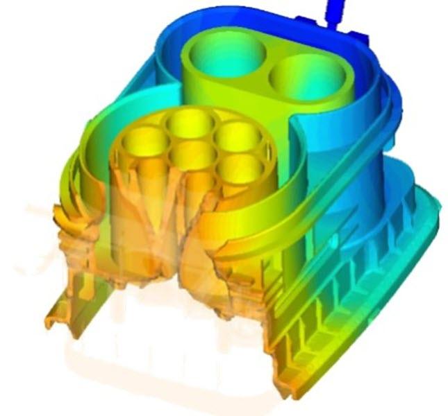
In addition, TE-Connectivity’s principal engineer of molding simulation, Patrick Bertram, felt that inclusion of mold simulation simultaneous to the quality process was key to accelerating innovation cycles. Bertram then convinced suppliers Volume Graphics and SIMCON to create an automated interface between the measurement and simulation-optimization software sets.
The full, multi-vendor integration allowed for greater use of model-based annotations and PMI, leading to a looping of virtual test and real-world measurement results back to design and FEA-mold simulation, and forward to prototyping, First Article Inspection (FAI) and production.
“We surprised people by implementing standards well before their final release dates,” says Stokowski. “Why wait 3-5 years when the directions, such how to display 3D annotations, are made clear in the ISO drafts?”
“STEP 214 and 242 didn’t work for our integration,” he says. “We used the Application Programming Interface (API) in the Creo toolkit and ISO-GPS to establish our direct interface to VGMETROLOGLY and VGSTUDIOMAX software. There are customized, added special functionalities that let us reuse values derived from FAI. And that’s it: Geometric Dimension & Tolerance (GD&T) capabilities from Creo and VGMETROLOGY, along with the integration of VARIMOS from SIMCON. No other software is needed to interconnect design and simulation with quality measurement.”
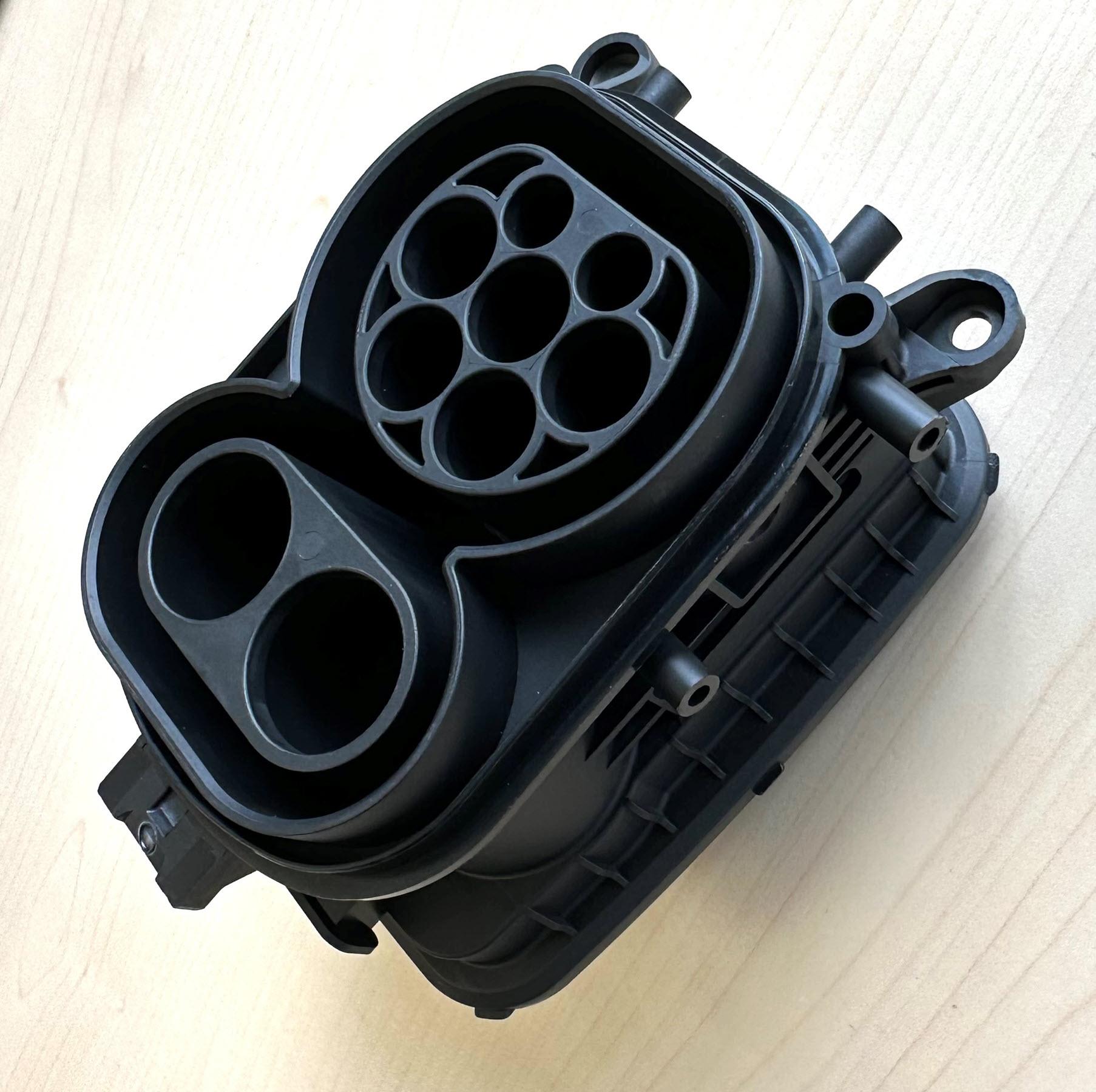
The first goal of TE Connectivity’s digital metrology program was to ensure that the as-designed parts matched the as-manufactured parts. In most cases, this means working with molded products with normal center-tolerance concerns in the tooling and typical push-out marks and small flaws. Mold simulation and virtual metrology help identify and resolve both functional and cosmetic aspects of producing molds and plastic parts. FAI leads to a feedback loop where 3D-model and simulation, mold, and manufactured part are reconciled and unified with few-to-no discrepancies. From there, quality templates are created from the Volume Graphics software for automated inspection.
“Ten or fifteen years ago designers didn’t really spend too much time thinking about the details coming out of the mold,” says Stokowski. “And much of that is taken care of now with tooling software and the automation loop we are creating. The full data is there for our interdisciplinary teams to see and use quickly.”
Quality’s return on investment (ROI)
The value of quality overall is not much debated. Quality builds brands, attracts customers and softens the back-end costs of warrantee claims, service labor, and revisiting process and design methods to find the root-cause of unanticipated problems.
On the other hand, financial managers often question all but fundamental operational investments and are happy with a profitable status quo. Engineers can find frustration in adapting systems that are new and even more complex than past programs. Investing in, learning and implementing quality upgrades can strain an organization in many ways.
“The real value of quality for TE Connectivity is the time we save,” says Stokowski. “Time and the value customers place on durable, reliable, superior products.”
He continues, “What is the value of four-to-six weeks of development time saved in engineering and potentially realized in shipping? How is that calculated against machine and software costs? There are no exact answers. “But we have a Centre of Excellence (CoE) that collaborates with customers, trains our personnel, and creates our quality infrastructure that contributes to innovation. That is a business value statement in and of itself.”
Time savings and the early engine-control unit
“We are on target for a ten-day turnaround for design, simulation, scanning and producing a digital metrology report,” says Stokowski. “So much is now going on upfront. We want as much done as possible before we hold a physical part.”
Volume Graphics has helped TE Connectivity in this frontloading and looping of data with their Adaptive Measurement Templates. The templates can classify, localize and segment defects using AI and Machine Learning. They also automate much of the scan analysis and then capture information for metrology reports. The goal at TE Connectivity is to lower analysis time from 10 days to five.
One of Stokowski’s “classic design cycle” projects was taking place just before the full 2014 CT digital analysis initiative that used Volume Graphics software. It entailed mold and part development of an engine-control unit. The unit, belonging to the automotive sector, had more than 200 electric-connection pins and was the first of its kind.
Says Stokowski: “It took nearly a year and more than ten iteration loops to bring the part into drawing requirements. It was an exhausting, never-ending story. And then just three-and-one-half years later, the first tooling replacement had to be done. You can imagine the team’s response! ‘Oh my goodness…we will need another year just to do the conditioning and correction loops,’ they thought, heads lowered,” he laughs.
“But by that time we already implemented the process of digital metrology, and we made the mold design within one loop,” he points out.
A goal to cut development times by 75%
Today, TE Connectivity hopes to cut their mold and part development process to 25 percent of the time it took in the past. There will always be some manual tasks, says Stokowski—a hands-on refinement of GD&T, or times to debate an issue, or resolve a digital discrepancy in the “thread” that links programs. There aren’t the resources, either, for every mold to go through Design of Experiments (DOE). But the company’s critical molds will use DOE and all new molds will pass through the VGMETROLOGY software.
Suppliers are taking on the new approach as well. Many have purchased virtual metrology systems of their own. Twenty-to-thirty percent of the external tool builders use the whole integrated digital system. Others go to scanning locations out-of-house and use the software internally. All tool builders do material compliance checking and basic measurements ahead of TE Connectivity conducting a full metrology report within the CoE.
Stokowski expects that eventually TE Connectivity’s quality process will be adapted by all suppliers, but that vision is not yet near-term—as cost and culture barriers exist for both GPS and virtual metrology. Meanwhile, his team and the CoE will work toward a future “push button” process even though they expect, for practical reasons, that it would apply to “seventy-five percent of our work,” says Stokowski.
As a result of their quality-process improvement approach, many advances and milestones have taken place for TE Connectivity:
- All new injection molded parts are implemented in MBD
- 100% of injection molded parts are scanned, and there are no more tactile measurements
- Part specifications are created in Creo to ISO-GPS standards and converted to a 3D PDF as a neutral document, where needed
- The integration between Creo and VGMETROLOGY software is direct
- 75% of all product data is transported via PMI
- Only isolated rework is done due to interface incompatibilities
For final part inspection, TE Connectivity has six scanners working inline in the EMEA region for injection molded parts. The scanners and Volume Graphics software look—post-metrology report—for key dimensions and targeted areas of a part rather than at the whole of the component. Costs and time weigh in here. But also, the upfront virtual design, analysis and testing of parts so early in creation, combined with checks during First Article Inspection, ensure that compliance has been met and rechecked on the factory floor. The company maintains 23 scanners worldwide, a global license for Creo, and complete suites of Volume Graphics’ software. And it operates a competence center for integrating and distributing these digital technologies.
Quality is the end game
Business debates about how much to invest in technology are perennial and the accounting science to unearth the facts is rarely used fully. But quality is the end game for many institutions and particularly for manufacturing. Quality is an aligning value that attracts customers, keeps customers, and centers engineering teams on what is important and so pervasive in its organizational impact.
“TE Connectivity’s quality tools and digital systems are telling us a lot about our products—how to improve them, why they behave in such a way, and how to spot and predict variation,” says Stokowski. “Most immediately, we are saving time and building great products that advance other fields such as e-mobility. “Virtual metrology and digitalization offer an endless box of treasures, if you chose to use them.”


