


Thomson Mathew, ANCA’s software product manager has a huge wealth of knowledge and expertise, having worked in the cutting tool industry for almost 25 years. The architect of many of ANCA’s market renowned software products – Thomson has written a technical guide on creating the perfect Endmill running through a five-part instructional series.
In this issue, we look at the factors which will impact the overall performance of an Endmill and “weird” Endmills that have higher geometrical levels of complexity.
PART ONE: GEOMETRY DESIGN AND PARAMETER VERIFICATION
Every Endmill begins with design and a well-designed geometry can make a high performance Endmill. There are many factors which will impact the overall performance of an Endmill. Four major ones that get cited are the grade or quality of carbide material, the cutting tool geometry design, the precision manufacturing process or quality control and the type of coating.
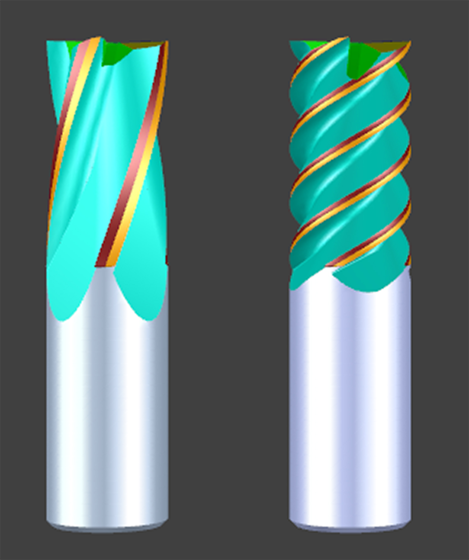
Low Helix (15 degrees) to High Helix (60 Degrees)
The hardness of an Endmill’s material, usually carbide, will depend on the grade of carbide in the matrix. Smaller grains mean more substance versus binder, and therefore a harder tool. Exotic coatings will improve lifespan and cutting performance. Quality control means a workshop can get a consistent result.
But geometry has an outsized role, one that highlights the blend of art and engineering – and for a long time, trial and error – involved in creating the ideal Endmill. This begins with design. Some of the important factors in Endmill design include the combination of both variable helix and index flute geometry design, core geometry design, the OD clearance angles eccentric versus facet reliefs design, endface design with wiper flats and pad grinding or end dubbing etc. each time from a set of Endmills.
As I have written elsewhere, the progress of the industry has seen Endmills grow increasingly “weird” as toolmakers have sought high material removal rates while avoiding “chatter”.
Regenerative chatter happens when the harmonics between a tool and workpiece are at different frequencies. The two self-excited objects will hit against each other, which is a negative for surface finish and dimensional accuracy, as well as the lifespan of the tool and machinery. It is a drain on productivity and profits.
High helix tools (over 35 degrees) have long been popular for their strength and fast feed and swarf removal rates. While they have these advantages over low helix Endmills for hard materials, they are also the more prone of the two to chatter. Some of the trial and error to combat this has been around variable helixes and pitches and trying to better balance tools. This has led to “weird” Endmills, with higher geometrical levels of complexity.
In high helix tools the cutting forces are directed more vertically and less horizontally, which reduces tool deflection and results in quick and efficient chip evacuation. More positive axial rake lowers cutting forces which helps to increase feedrates. The core of the tool is thicker due to the shape of the helix and the tool is stronger. High helix Endmills are typically used in tougher harder materials because they wear better, although they can also be used in softer materials like aluminium. One disadvantage of high helix Endmills is the tendency to chatter more, and they really bite into the material.
On the contrary, low helix tools are less likely to chatter and typically perform better in soft materials. Their disadvantage is the lower feedrates and hence lower material removal rates. Our understanding of how to mitigate chatter has come a long way and involves no guesswork nowadays. The geometry and design are purely based on material to be cut whether it is soft or hard.
Variable helix end mills with variable index are considered state of the art these days. The idea is to vary the helix along the flute length or from flute-to-flute. The aim of the variable helix is to fight chatter. Since chatter is a resonance effect, anything we can do to break up the resonance of the flutes beating against the workpiece will reduce chatter. The tool balancing capabilities in the RN34 release of ANCA’s ToolRoom software is the perfect solution to combat chatter.
About ANCA
ANCA is a market leading manufacturer of CNC grinding machines. It was founded in 1974 in Melbourne, Australia where the company still has its global headquarters. ANCA has offices in the UK, Germany, China, Thailand, India, Japan, Brazil and the USA as well as a comprehensive network of representatives and agents worldwide.
ANCA CNC grinders are used for manufacturing precision cutting tools and components across a diverse range of competitive industries including cutting tool manufacture, automotive, aerospace, electronics and medical.


